Network
Use the network settings to configure Cellular, WAN, WAN(STA), VLAN, Switch WLAN Mode, WLAN Client, Link Backup, VRRP, IP Passthrough, Static Route, OSPF
Cellular
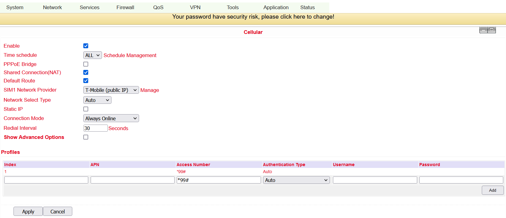
In this menu area you define and configure the dial-up of your router. Can be reached via Network > Cellular.
Name |
Description |
Default |
|---|---|---|
Enable |
Activates the dialup function |
Enabled |
Time Schedule |
Set time for online and offline (see also 3.2.1.1) |
ALL |
Shared Connection (NAT) |
Enabled - device connected to router |
Enabled |
Default Route |
Mobile radio interface as standard route to the Internet |
Enabled |
Network Provider (ISP) |
Select local ISP, if not listed here, select “Custom” |
Custom |
APN |
APN parameters supplied by the provider |
internet.t-d1.de (Telekom) |
Access Number |
Dial-up parameters provided by the local ISP |
*99***1# |
Username |
Username provided by the provider |
tm |
Password |
Password provided by the local ISP |
tm |
Network Select Type |
Select mobile network type (2G, 3G, 4G only) |
Auto |
Connection Mode |
Connection mode: Router is always online |
Always Online |
Redial Interval |
If dial-up fails, the TC router dials again after this interval |
30 Seconds |
Show Advanced Options |
Allows configuring advanced options |
Disabled |
PIN Code |
Field for the PIN number of the SIM card |
Blank |
MTU |
Set MTU (Maximum Transmission Unit) |
1500 |
Authentication Type |
PAP, CHAP |
Auto |
Use Peer DNS |
Enable this option to accept peer DNS |
Enabled |
Link Detection Interval |
Set interval for connection detection (0 = disabled) |
55 Seconds |
Debug |
Enable debug mode |
Disabled |
Debug Modem |
Enable Debug Modem |
Disabled |
ICMP Detection Mode |
Monitor Traffic: Only when no data is flowing, a Keep Alive ping is sent at regular intervals |
Monitor Traffic |
ICMP Detection Server |
Set server for ICMP detection; empty field means none is available |
Blank |
ICMP Detection Interval |
Set interval for ICMP detection |
30 Seconds |
ICMP Detection Timeout |
Set timeout for ICMP detection (TK500 is restarted on ICMP timeout) |
20 Seconds |
ICMP Detection Retries |
Set maximum number of retries if ICMP fails |
5 |
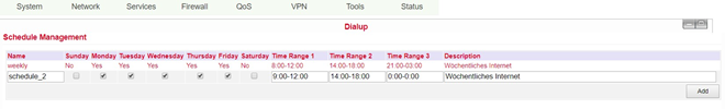
Schedule Management
Schedule management (next to “Time schedule”):

Here you can run your own dialup strategy, i.e. you can define here over three time ranges when the router should be online.
Name |
Description |
Default |
|---|---|---|
Name |
Name for the schedule |
Schedule_1 |
Sunday |
Sunday |
Blank |
Monday |
Monday |
Enabled |
Tuesday |
Tuesday |
Enabled |
Wednesday |
Wednesday |
Enabled |
Thursday |
Thursday |
Enabled |
Friday |
Friday |
Enabled |
Saturday |
Saturday |
Blank |
Time Range 1 |
Set time range 1 |
9:00-12:00 |
Time Range 2 |
Set time range 2 |
14:00-18:00 |
Time Range 3 |
Set time range 3 |
0:00-0:00 |
Description |
Describe configuration |
Blank |
You can also create multiple schedules if, for example, different working hours apply on one working day.
WAN
Here you can set up a new WAN (Wide Area Network). To be reached via Network > WAN.
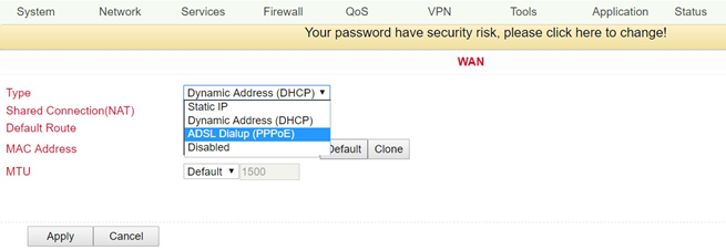
On this page the type of the WAN port can be set:
Name |
Description |
Default |
|---|---|---|
Type |
Static IP |
Disabled |
Only one WAN type can be enabled at a time. Enabling one type disables another.
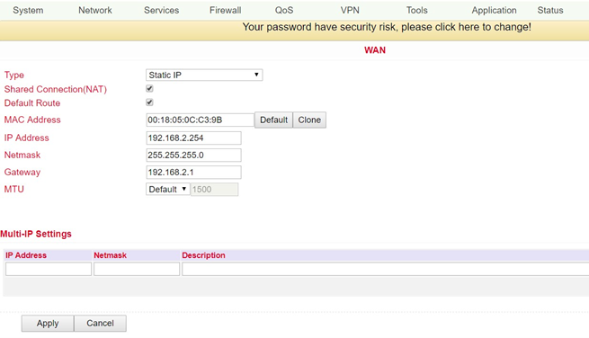
Static IP
Name |
Description |
Default |
|---|---|---|
Type |
Static IP |
Disabled |
Shared Connection (NAT) |
Enabled - local device connected to router can access the Internet |
Enabled |
Default Route |
Mobile radio interface as standard route to the Internet |
Enabled |
MAC Address |
Set MAC address (button Default = standard, Clone = newly created MAC address) |
Default |
IP Address |
Set IP address for WAN port |
192.168.1.29 |
Netmask |
Set netmask for WAN port |
255.255.255.0 |
Gateway |
Set WAN gateway |
192.168.1.1 |
MTU |
Set the maximum transmission unit (MTU), the options “Default” and “Manual” are possible |
Default = 1500 |
“Multi-IP Settings” (a maximum of 8 additional IP addresses can be set) |
||
IP Address |
Set another IP address for LAN |
Blank |
Netmask |
Set netmask |
Blank |
Description |
Describe settings |
Blank |
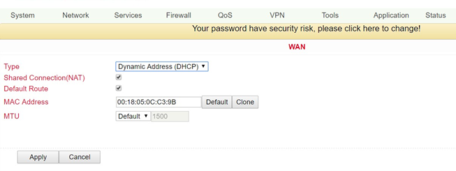
Dynamic Address (DHCP)
Name |
Description |
Default |
|---|---|---|
Type |
Dynamic Address (DHCP) |
|
Share Connection (NAT) |
Enabled - local device connected to router can access the Internet |
Enabled |
Default Route |
Mobile radio interface as standard route to the Internet |
Enabled |
MAC Address |
Set MAC address |
|
MTU |
Set the maximum transmission unit (MTU), the options “Default” and “Manual” are possible |
Default = 1500 |
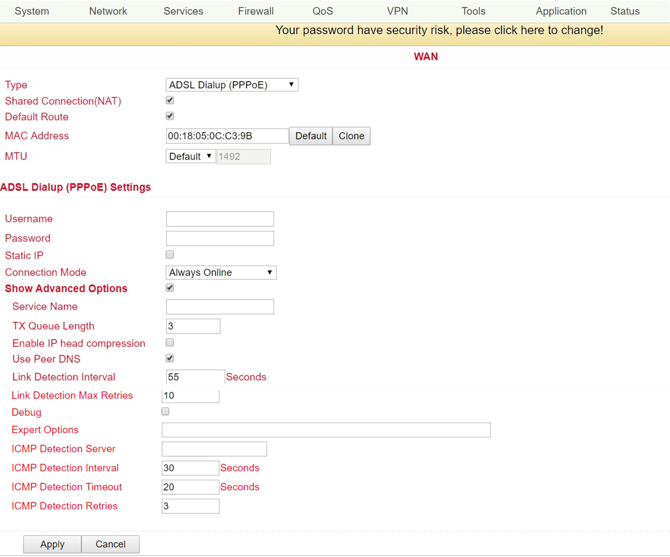
ADSL Dialup (PPPoE)
Name |
Description |
Default |
|---|---|---|
Type |
ADSL Dialup (PPPoE) |
|
Share Connection (NAT) |
Enabled - local device connected to router can access the Internet |
Enabled |
Default Route |
Mobile radio interface as standard route to the Internet |
Enabled |
MAC Address |
Set MAC address |
|
MTU |
Set the maximum transmission unit (MTU), the options “Default” and “Manual” are possible |
Default = 1492 |
ADSL Dialup (PPPoE) Settings |
||
Username |
Set user name to dial in |
Blank |
Password |
Set password to dial in |
Blank |
Static IP |
Enable static IP addresses |
Disabled |
Connection Mode |
Set connection mode (“Connect on Demand”/”Always Online”/”Manual”) |
Always Online |
Show Advanced Options/erweiterte Optionen |
||
Show advanced options |
Enable advanced configuration |
Disabled |
Service Name |
Here you can assign a name for the service |
Blank |
TX Queue Length |
Set the length of the transfer queue |
3 |
Enable IP head compression |
Click to enable IP header compression |
Blank |
User Peer DNS |
Enable peer DNS for users |
Disabled |
Link Detection Interval |
Set interval for connection detection |
55 Seconds |
Link Detection Max Retries |
Set maximum number of repetitions for connection detection |
10 (times) |
Debug |
Select to enable debug mode |
Disabled |
Expert Options |
Set expert parameters |
Blank |
ICMP Detection Server |
Set server for ICMP detection |
Blank |
ICMP Detection Intervall |
Set time for ICMP detection |
30 |
ICMP Detection Timeout |
Set timeout for ICMP detection |
3 |
ICMP Detection Retries |
Set maximum number of retries for ICMP detection |
3 |
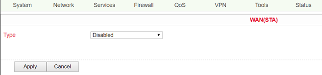
WAN(STA)
Under this menu item Network > WAN(STA) you can configure the TK500 as a WAN station. The settings in this menu item are the same as those in the WAN settings.
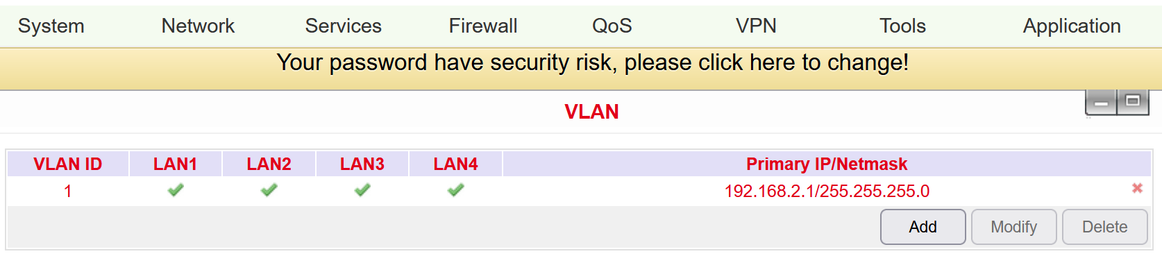
VLAN
A Virtual Local area Network (VLAN) is a logical subnet within a switch or an entire physical network. A VLAN separates physical networks into subnets by ensuring that VLAN-capable switches do not forward the frames (data packets) of one VLAN to another VLAN. This happens even though the subnets may be connected to common switches.
VLAN table
In the VLAN table you can change the assignment of VLANs to FastEthernet ports and create new VLANs.
Port Mode
In the Port Mode menu, different VLAN IDs can be assigned to the network ports FastEthernet LAN1 to LAN4.
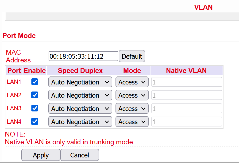
The options Acces and Trunk are available for the FastEthernet ports. In Access Mode, VLAN1 is always selected. In Trunk Mode you can assign VLAN IDs between 1-4000, which you have created before, to the FastEthernet ports.
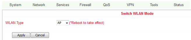
Switch WLAN Mode
Settings for the WLAN type can be made here. A distinction is made between Access Point (AP) and Station (STA). This can be accessed under Network > Switch WLAN Mode.
Name |
Description |
Default |
|---|---|---|
AP |
Access Point Mode |
AP |
STA |
Client Mode |
If WLAN TYPE STA (for station) is selected, the menu under Network changes. It is then possible to configure WAN(STA) under 3.2.3 and to set up only one client for an existing WLAN under 3.2.6.a WLAN Client.
WLAN Client
If the item STA was selected as WLAN type when configuring the Switch WLAN Mode (see 3.2.6.), it is no longer possible to configure a WLAN. You can then only configure the TK 500 as a WLAN client. This then works under Network > WLAN Client.
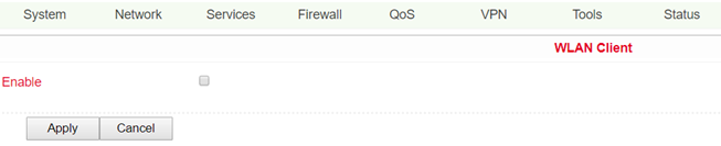
To configure the router as a WLAN client, please click Enable.
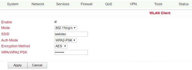
Now enter the data to connect the TK500 to an existing WLAN.
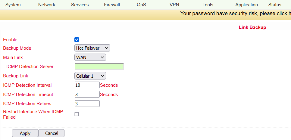
Link Backup
This option secures connections between wireless WAN and Ethernet WAN. If one WAN fails, the TK500 automatically uses the other. You can configure this under Network > Link Backup.
Name |
Description |
Default |
|---|---|---|
Enable |
Activate the service for connection backup |
Disabled |
Main Link |
Selection of WAN, dialup and WAN(STA) as main WAN possible |
WAN |
ICMP Detection Server |
ICMP can ensure a connection to a specific destination |
Blank |
ICMP Detection Interval |
Time interval between ICMP packets |
10 |
ICMP Detection Timeout |
Timeout for the individual ICMP packets |
3 (Seconds) |
ICMP Detection Retries |
If no retry of ICMP detection was successful, the backup connection is selected |
3 |
Backup Link |
Select backup connection |
Dialup |
Backup Mode |
Hot Backup / Cold Backup |
Hot Backup |
VRRP
The Virtual Router Redundancy Protocol (VRRP) is a method for increasing the availability of important gateways in local networks by means of redundant routers. Several physical routers are combined into a logical group. This group of routers now presents itself in the network as a logical virtual router. For this purpose, the logical router is assigned a virtual IP address and a virtual MAC address. One of the routers within the group is defined as the virtual master router, which then binds the virtual MAC address and the virtual IP address to its network interface and informs the other routers of the group, which act as virtual backup routers. You can set up this function under Services > VRRP.
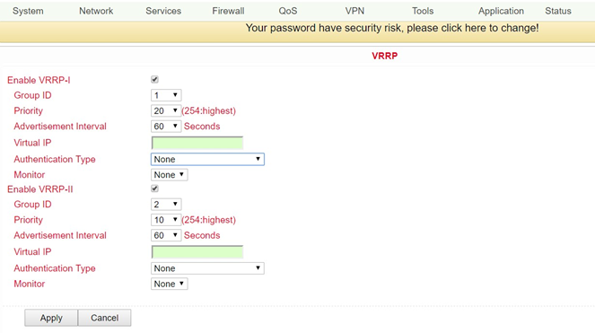
The TK500 series offers the possibility to create two different VRRP (VRRP I and VRRP II) groups.
Name |
Description |
Default |
|---|---|---|
Enable VRRP-I |
Select to activate VRRP |
Disabled |
Group ID |
Select group ID for router (range 1-255) |
1 |
Priority |
Select priority for router (range 1 - 254) |
20 (the larger the number, the higher the priority) |
Advertisement Interval |
Set advertisement interval |
60 Seconds |
Virtual IP |
Set virtual IP for the group |
Blank |
Authentication Type |
Optional: Typ „None/Password Authentication“ |
None. If Password Authentication is selected, a password can be assigned |
Virtual MAC |
Virtual MAC address |
Disabled |
Monitor |
Checking the WAN connection |
None |
Enable VRRP-II |
Select to activate VRRP |
Disabled |
Group ID |
Select group ID for router (range 1-255) |
2 |
Priority |
Select priority for router (range 1 - 254) |
10 (the larger the number, the higher the priority) |
Advertisement Interval |
Set advertisement interval |
60 Seconds |
Virtual IP |
Set virtual IP for the 2nd group |
Blank |
Authentication Type |
Optional: Typ „None/Password Authentication“ |
None. If Password Authentication is selected, a password can be assigned |
Virtual MAC |
Virtual MAC address |
Disabled |
Monitor |
Checking the WAN connection |
None |
IP Passthrough
Here you can assign the WAN IP to a device connected to a LAN port.
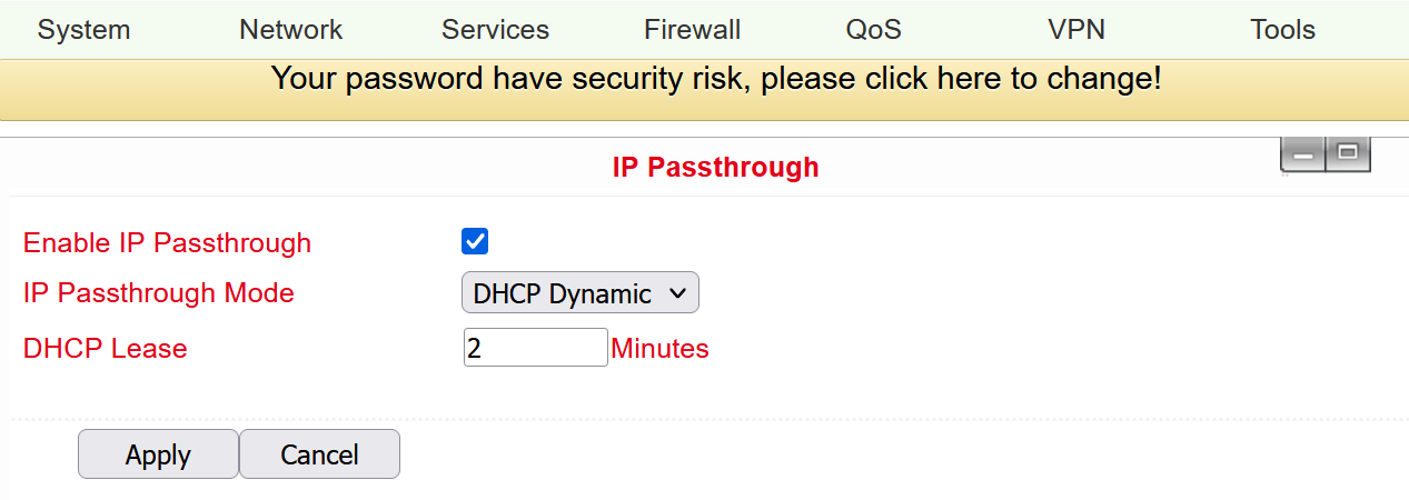 Only one device can obtain this IP address and access the Internet.
The LAN port should be of the Static type.
The function does not work with a link backup.
Only one device can obtain this IP address and access the Internet.
The LAN port should be of the Static type.
The function does not work with a link backup.
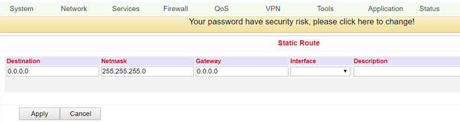
Static Route
Here it is possible to add static routes. Static routes provide your router with additional routing information. Under normal circumstances, the router has sufficient information when configured for Internet access, and no additional static routes need to be configured. Static routes need to be set only in exceptional circumstances, such as when your network contains multiple routers or IP subnets. You can add static routes under Network > Static Route by clicking the Add button.
Name |
Description |
Default |
|---|---|---|
Destination |
Set IP address of the destination |
Blank |
Netmask |
Set subnet mask of the destination |
255.255.255.0 |
Gateway |
Set gateway of the destination |
Blank |
Interface |
Optional LAN/WAN port access to target |
Blank |
Description |
Freely selectable name for the static route |
Blank |
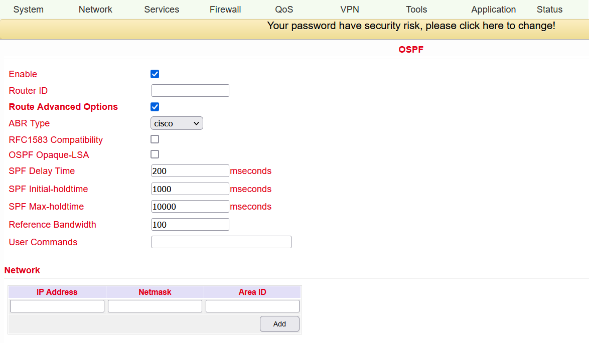
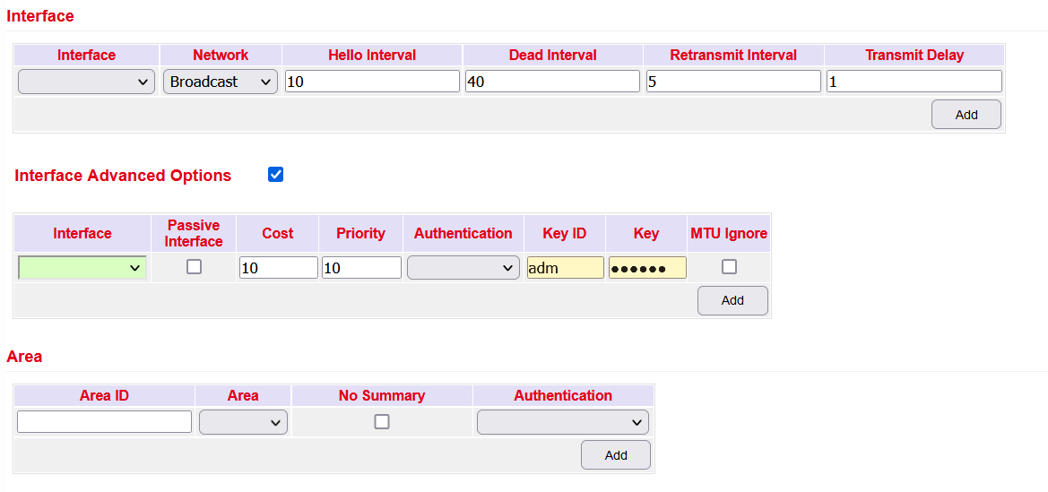
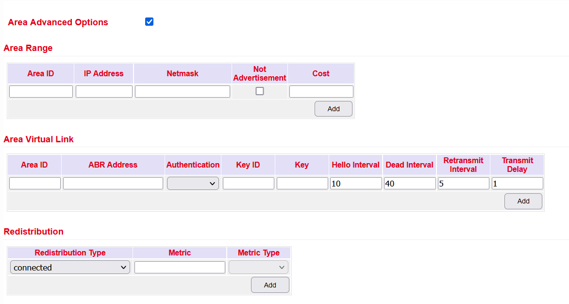
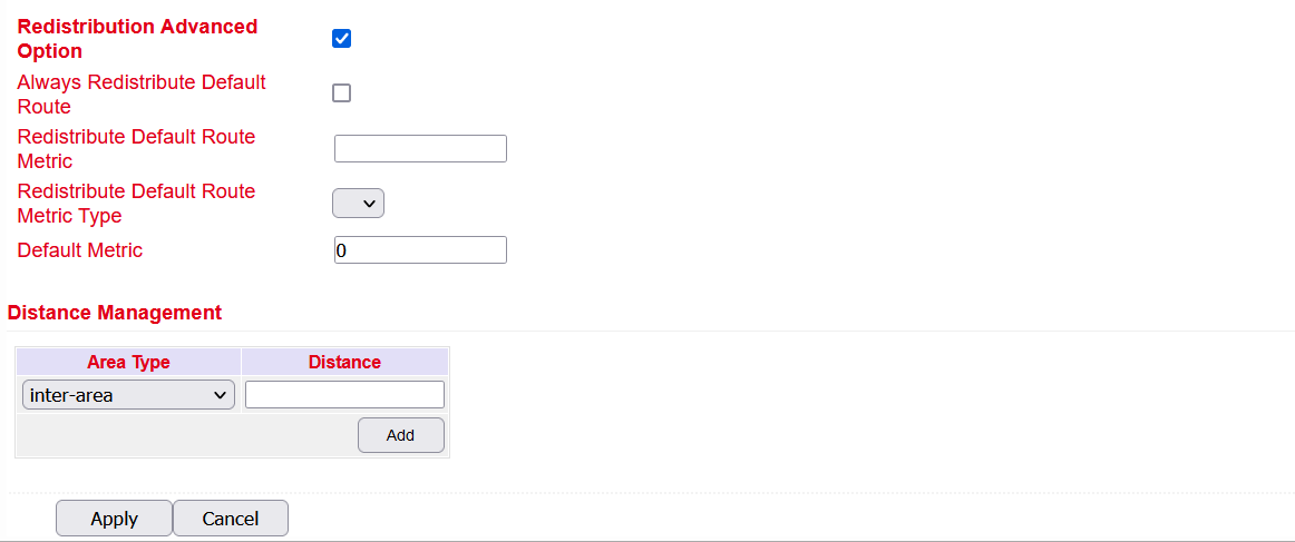
OSPF
Open Shortest Path First refers to a link-state routing protocol developed by the IETF.
This is a protocol for dynamic routing in IP networks. Dynamic routing detects changes in the network independently by the routers exchanging information with each other. The routing tables adapt dynamically to the respective situation.
Optimal routes to a destination can be determined based on various properties and metrics such as the number of hops, the bandwidth, the utilization of a link or configured costs. Failures of individual links are detected and alternative paths are calculated within a short time.